Grade 8 - Session 8: Ohm’s Law: Exploring Ohmic & Non-Ohmic Materials
Architect: Aleeza Ayaz & Shayaan Haider- Markhor3D
Session Length: 50-60 minutes
Learning Objectives:
In this session, students will:
- Recall and expand on concepts of voltage, current, and resistance.
- Understand Ohm’s Law and the conditions under which it holds true.
- Distinguish between ohmic and non-ohmic conductors based on their behavior.
- Practice correct measurement techniques, understanding why voltage is measured in parallel and current in series.
- Analyze and plot V vs. I graphs for both ohmic and non-ohmic conductors.
Teacher Resource:
Session File:
Equipment Required:
- MeasureLab with voltage and current sensors.
- Fixed resistor (ohmic conductor) and a filament bulb or diode (non-ohmic conductor).
- Breadboard and connecting wires.
- Power source with adjustable voltage.
- Laptop or PC to display live measurements.
- Worksheet for recording observations and plotting graphs.
- Pens, pencils, markers, etc.
Introduction and Hands-On Exploration (30-35 minutes)
Recalling the Basics of Voltage, Current, and Resistance
-
Engaging with Simple Questions
- You may ask:
“Have you ever noticed how water flows through a garden hose? What might make the water flow stronger or weaker?” - Guide students to relate this to electrical flow, explaining that voltage is like the pressure pushing the flow, and current is the flow of electricity itself.
- You may ask:
-
Re-explaining Voltage and Current in Simple Terms
- Voltage as Push
- You may explain:
“Imagine voltage as the pressure pushing water through a hose. The higher the voltage, the stronger the push driving electricity through a circuit.”
- You may explain:
- Current as Flow
- You may explain:
“Now, if voltage is the push, current is like the actual water flow moving through the hose. The stronger the push (voltage), the more current (electric flow) moves.”
- You may explain:
- Voltage as Push
-
Introducing Resistance
- You may ask:
“What would happen if we squeezed the hose in the middle? Would the water flow stay the same, or would it slow down?” - Explain:
“This squeeze is similar to resistance in a circuit, which slows down the flow of electricity. Different materials and components can resist the flow to varying degrees.”
- You may ask:
-
Understanding How Voltage, Current, and Resistance Interact (Ohm’s Law)
- You may explain:
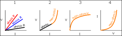
“In circuits with a fixed resistance, voltage and current are related by a rule called Ohm’s Law, which says: V = IR . This means that for a constant resistance, if we increase voltage, current will also increase proportionally.”
- You may explain:
Setting Up the Experiment to Verify Ohm’s Law with an Ohmic Conductor
-
Building a Simple Circuit with a Fixed Resistor
- Guide students to set up a circuit with a fixed resistor (e.g., 100Ω) as an ohmic conductor.
- You may explain:
“Resistors are a good example of an ohmic conductor because they follow Ohm’s Law at all temperatures, maintaining a constant resistance as voltage changes.”
-
Voltage in Parallel, Current in Series
- You may ask:
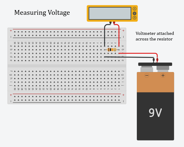
“Why do you think we measure voltage across (in parallel with) a component instead of along the same path as current?” - Explain:
“Voltage is like a push, so we measure it across the points between which the ‘push’ or potential difference is applied. If we connected the voltmeter in series, we would only get part of the push because voltage divides among components in series.”
- You may ask:
- You may then ask:
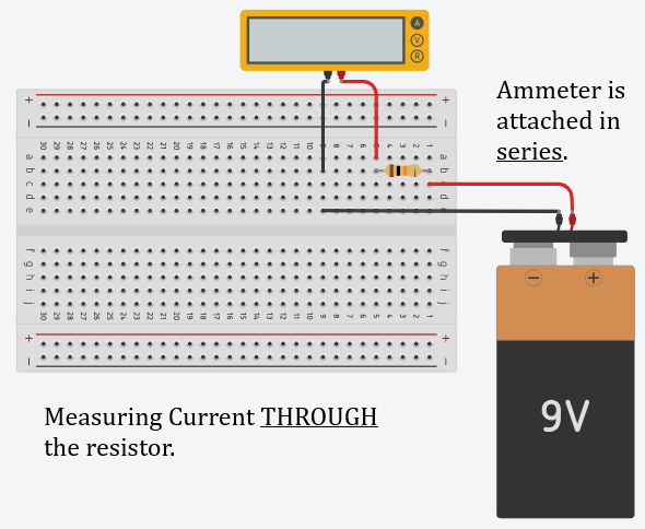
“And why do you think we measure current in series?” - Explain:
“Current is the flow itself, so we measure it along the path where the flow goes through. If we put the ammeter in parallel, it would split the flow, giving us an inaccurate reading.”
Experimenting with the Resistor (Ohmic Conductor)
-
Adjusting Voltage to Measure Current
- Students will adjust the voltage across the resistor in steps (e.g., 1V, 2V, 3V) and record the resulting current.
- You may ask:
“What do you predict will happen to the current as we increase the voltage? Will it change proportionally?”
-
Recording Data and Calculating Resistance
- For each voltage setting, students record the current and calculate resistance using R = V/I to confirm it remains constant.
| Voltage (V) | Current (I) | Calculated Resistance (R = V/I) |
|---|---|---|
| 1 V | ||
| 2 V | ||
| 3 V | ||
| 4 V | ||
| 5 V |
- Creating a V vs. I Plot
-
Students will plot V (x-axis) vs. I (y-axis) to observe a straight line, confirming that voltage and current are proportional for ohmic conductors.
-
You may ask:
“What does the shape of this line tell us about the relationship between voltage and current?” -
Explain:
“The straight line indicates that voltage and current are proportional for this component, confirming it follows Ohm’s Law.”
-
Experimenting with a Non-Ohmic Conductor (e.g., Filament Bulb or Diode)
-
Setting Up the Circuit with a Filament Bulb
- Have students replace the resistor with a filament bulb or diode.
- Explain Non-Ohmic Behavior:
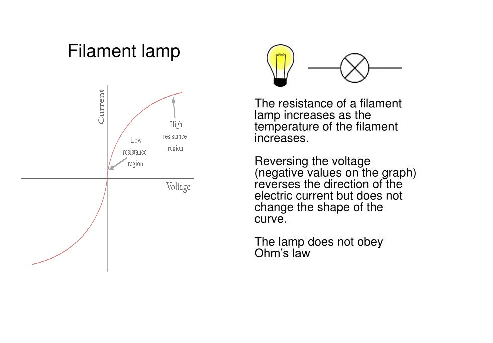
“A filament bulb is a non-ohmic conductor because as it heats up, its resistance increases. So, the relationship between voltage and current will not be proportional, unlike with a resistor.”
-
Measuring Voltage and Current Across the Filament Bulb
- Students will again adjust the voltage in steps and record the current through the bulb.
| Voltage (V) | Current (I) | Calculated Resistance (R = V/I) |
|---|---|---|
| 1 V | ||
| 2 V | ||
| 3 V | ||
| 4 V | ||
| 5 V |
- Creating the V vs. I Plot for the Non-Ohmic Conductor
- Guide students to plot V vs. I for the filament bulb.
- You may ask:
“Do you notice a difference in the shape of this plot compared to the resistor?”
- Explain Non-Proportionality:
“The curved line shows that voltage and current are not proportional. As the filament heats up, resistance increases, so current doesn’t increase as much for each increase in voltage. This non-linear behavior means the bulb does not follow Ohm’s Law at all points.”
Reflection and Follow-Up Questions (15-20 minutes)
-
Understanding Ohmic vs. Non-Ohmic Conductors
- You may ask:
“What was the difference between the resistor and the filament bulb in terms of Ohm’s Law? Why do you think one followed the law and the other didn’t?” - Help students conclude that the resistor’s resistance remained constant, while the filament bulb’s resistance changed with temperature, making it a non-ohmic conductor.
- You may ask:
-
Conditions for Ohm’s Law
- You may ask:
“What conditions must be met for a material to follow Ohm’s Law? Does the type of material or how it’s used make a difference?” - Guide students to understand that for a material to follow Ohm’s Law, its resistance should stay constant, as it does in many metals at consistent temperatures.
- You may ask:
Summary and Wrap-Up (5 minutes)
- Summarize Key Learnings:
- “Today, we explored voltage, current, and resistance, measured in circuits with ohmic and non-ohmic conductors. We learned that Ohm’s Law only applies to conductors that maintain constant resistance.”
- Real-Life Connection:
- “In electronics, it’s essential to know how components behave under different conditions. Understanding these principles helps engineers design circuits with stable or varied resistance, depending on what the device needs to do.”
Glossary
- Voltage: The force that drives electricity through a circuit.
- Current: The flow of electric charge through a circuit.
- Resistance: The opposition to the flow of electric current.
- Ohm’s Law: The principle that voltage equals current times resistance, represented as V = IR .
- Ohmic Conductor: A material that maintains constant resistance and follows Ohm’s Law.
- Non-Ohmic Conductor: A material with variable resistance that does not follow Ohm’s Law.