Grade 8 - Session 9: “Building and Testing a Our Own Light Sensor”
Architect: Aleeza Ayaz & Shayaan Haider - Markhor3D
Session Length: 50-60 minutes
Learning Objectives:
In this session, students will:
- Build a basic light sensor using an LDR and MeasureLab.
- Understand the concept of a potential divider and how it helps measure changes in light intensity.
- Use MeasureLab to observe and record voltage changes in different light environments.
- Analyze and compare data to draw conclusions about light intensity in various locations.
- Explore practical applications of light sensors and how light measurement is used in real-world technology.
Teacher Resource:
Session File:
Equipment Required:
- PC/Laptop to display measurement and live plot.
- Breadboard for circuit building.
- Light Dependent Resistor (LDR).
- Fixed resistor (e.g., 10kΩ) for the potential divider circuit.
- Jumper wires to connect components.
- Battery or power source (e.g., 9V battery or power supply).
- MeasureLab with a built-in voltage probe to measure voltage changes.
- Worksheet for recording observations.
- Pens, pencils, markers, etc.
Teaching Aids:
- Visual aids: Diagrams of potential divider circuits, light sensors, and real-world applications.
- Projector (optional) to display real-time voltage plots from MeasureLab.
Introduction and Hands-On Exploration (15-20 minutes)
Engaging Students with Real-World Examples of Light Sensors:
We have worked with the light sensor in the MeasureLab. Today we will learn how we can make one, ourselves!!!
-
Start with a Question:
-
You may ask:
“Have you ever noticed how street lights turn on automatically at night or how some devices adjust screen brightness based on lighting? How do you think they detect light?” -
Allow students to share their ideas and experiences with automatic lights or devices that react to light.
-
-
Introducing Light Sensors and Their Uses
- You may explain:
“These devices use light sensors to detect how much light is in their environment. When it’s dark, they activate lights, adjust brightness, or even control temperature. Today, we’re going to build our own light sensor and use it to measure light intensity in different locations around us.”
- You may explain:
-
Introducing the Light Dependent Resistor (LDR):
-
You may ask:
“If you had to design a light sensor, what kind of component would you need that could sense light and change something we can measure?” -
Introduce the LDR:
“We’ll use a Light Dependent Resistor, or LDR. This is a resistor that changes its resistance based on the light around it. In bright light, it has low resistance, and in the dark, it has high resistance. We can measure this change in resistance using a circuit called a potential divider.”
-
Step 1: Setting Up the Light Sensor Circuit
-
What is a Potential Divider?
-
You may ask:
“If the LDR changes resistance based on light, how can we convert this into a measurement we can see and track?” -
Explain the potential divider concept:
“A potential divider circuit splits the voltage between two components. As the LDR’s resistance changes with light, the voltage across it also changes. We’ll measure this voltage using MeasureLab, and it will help us track the light intensity in different places.”
-
-
Building the Circuit on a Breadboard
- Guide Students Through the Setup:
- Place the LDR on the breadboard.
- Connect one leg of the LDR to the positive terminal of the power source.
- Connect the other leg of the LDR to a 10kΩ resistor in series, and connect the other end of the resistor to ground (negative terminal of the battery).
- Jumper wires: Connect a wire from the point where the LDR and resistor meet to MeasureLab’s voltage probe for monitoring voltage changes.
- Guide Students Through the Setup:
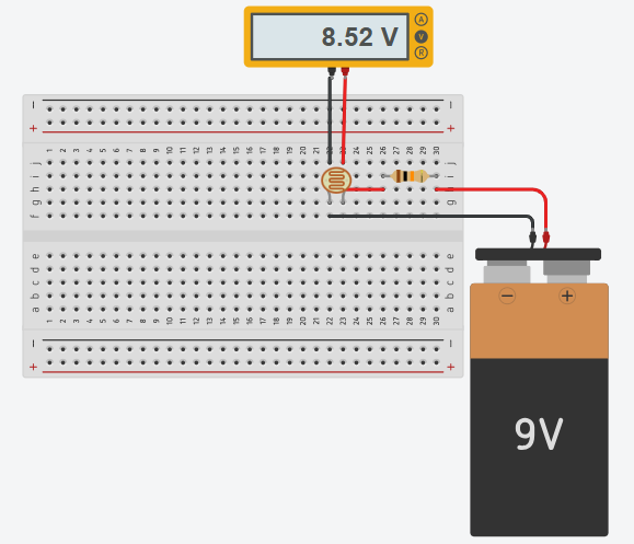
Step 2: Testing the Light Sensor in Different Environments (20-25 minutes)
-
Introduce the Experiment
-
You may say:
“Now that we’ve built a light sensor, let’s test it in different environments to see how it responds to various light levels.” -
Explain the Setup:
“We’ll place our sensor in different locations with different lighting, like in a bright spot near the window, under a desk, in a shaded area, or in a closed box. MeasureLab will show us how the voltage changes based on the light level.”
-
-
Moving the Sensor to Different Locations and Recording Data
-
Students should record the voltage in different light conditions:
Environment Voltage (V) Light Level (High/Medium/Low) Bright Spot (e.g., window) Shaded Area (e.g., under desk) Indoor Lighting (e.g., center of room) Dark Area (e.g., inside a box)
-
-
Observe and Discuss Changes at Each Step
- At Each Location:
-
You may ask:
“What do you notice about the voltage in this location? Why do you think it’s higher (or lower) here?” -
Explain as Needed:
“Higher voltage here means less light is hitting the LDR, increasing its resistance. In bright areas, the voltage will be lower because the LDR’s resistance decreases.”
-
- At Each Location:
Step 3: Analyzing and Comparing the Data (10-15 minutes)
-
Discuss Observations
- You may ask:
“What patterns do we see in the voltage readings across different light environments? Which area had the highest voltage, and which had the lowest?”
- You may ask:
-
Exploring Real-World Applications
- You may explain:
“Light sensors are useful in many real-world applications. For example, in a security system, a sudden light change can trigger an alert. In agriculture, light sensors help farmers monitor sunlight levels for crops. Even in cars, sensors adjust dashboard brightness based on the surrounding light.”
- You may explain:
-
Recording Observations and Identifying Trends
-
Guide students to organize their results in a table and draw a conclusion:
- Example Question:
“Which environment had the highest light intensity based on your voltage readings? What do you think this means about light in that area?”
- Example Question:
-
Reflection and Discussion (5-10 minutes)
-
Summarize Key Learnings
- You may summarize:
“Today, we learned how to build a basic light sensor using an LDR and MeasureLab. We saw how voltage changes with light intensity and how we can use this to measure light levels in different environments.”
- You may summarize:
-
Real-World Connection
-
You may ask:
“Where else might you see light sensors being useful? How could this technology improve daily life or help in specific fields?” -
Guide students to think about fields like healthcare (measuring light for patient care), urban planning (for streetlights), or environmental monitoring (for tracking sunlight in natural areas).
-
Glossary
- Light Dependent Resistor (LDR): A resistor that changes resistance based on light intensity.
- Potential Divider: A circuit that divides voltage between two components, useful in sensors.
- Voltage: The electrical potential difference that changes based on light level in this experiment.
- Resistance: The opposition to the flow of current, which changes with light in the LDR.
- Light Sensor: A device used to measure light intensity by changing resistance or voltage in response to light.