1. Introduction
The Z-axis limit switch is a critical safety and calibration component. It tells the printer exactly where the “Home” (Z=0) position is. If this switch is incorrectly positioned, it can lead to failed prints or even damage to the print bed. This guide will help you diagnose and calibrate the triggering mechanism for a perfect first layer.
2. Why Adjust the Z-Limit Switch?
In an ideal homing sequence, the nozzle should descend until it almost touches the bed, triggered precisely by the limit switch. You may need to adjust this if:
- Homing Too Early: The nozzle stops in mid-air, far above the bed.
- Homing Too Late: The nozzle pushes into the bed, causing the motors to grind or the bed to flex.
For reference a normal homing sequence looks like this.
3. Diagnosis: Signs Your Switch Needs Adjustment
Before making mechanical changes, check for these three signs:
- Visual Gap: During the homing sequence, the nozzle is visibly too high or is physically colliding with the build plate.
- Extrusion Issues:
- Too Low: The nozzle is so close that filament cannot escape (clogging behavior).
- Too High: Filament curls into “spaghetti” and doesn’t stick to the bed.
- ABL Failure: In most cases, if the physical limit switch is out of range, the Automatic Bed Leveling (ABL) system will fail to initialize or return an error.
4. Adjustment Procedure
To adjust the trigger point, we will modify the position of the screw mechanism on the Z-axis.
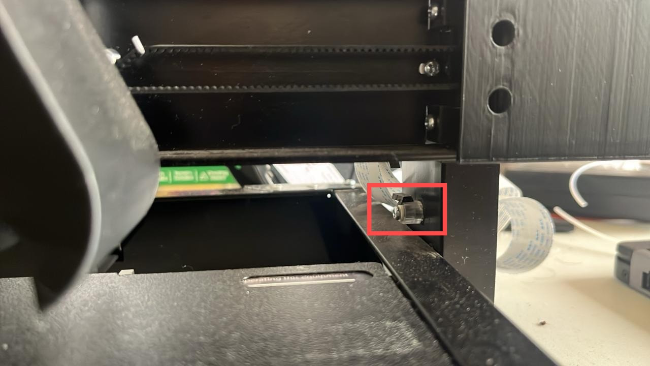
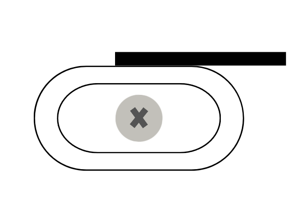
It is the red marked part in the image above. The part should be similar to the following illustration:
If your part is does not look like this, chances are it might be broken or damaged during transit. In that case, either the black strip on top will be damaged or completely missing:
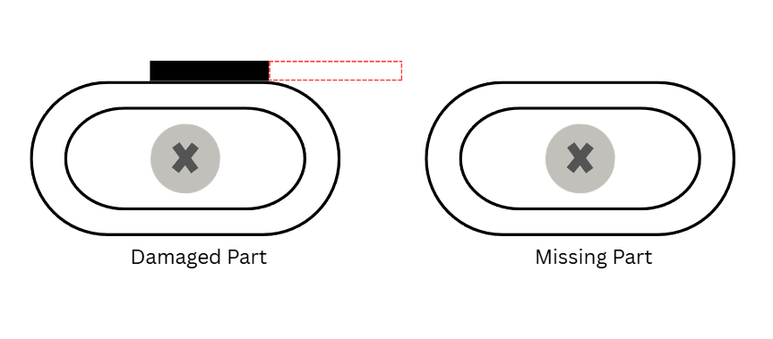
In either case, you need to fix it before proceeding ahead.
Fixing the Trigger Mechanism:
To fix it, you need a card. A good quality business card should do the trick. You just need something thin enough to be placed on the part and rigid enough that it triggers the switch.
You need to cut a small piece of it. An ideal measurement should be 0.5 cm wide and 2.5 cm long although it can be slightly off as long as the piece does not hinder the printer’s movement.
Once cut, place the piece in the same orinetation as shown in the original image. After that, now you can move to calibrating your trigger.
Calibrating the Z Limit Switch:
- Locate the Mechanism: Find the small adjustment screw on the Z-axis trigger assembly (as shown in the image above).
- Loosen the Screw: Use the appropriate screwdriver to slightly loosen the screw. Do not remove it completely; just loosen it enough so the mechanism can move up and down.
- Calibrate the Height:
- If the printer homes too early (Gap is too big): Move the triggering mechanism downwards slightly.
- If the nozzle pushes into the bed: Move the triggering mechanism upwards slightly.
- Secure and Test: Tighten the screw back into place.
- Iterate: Home the printer again. You may need to repeat this process 2–3 times to find the “sweet spot” where the nozzle sits perfectly at the bed surface level.
5. Conclusion
Once the Z-limit switch is correctly set, your ABL will function correctly, and your first layers will have the perfect “squish” for successful prints.
Happy Printing! If you encounter further issues, feel free to reach out on the Markhor3D Community Forum.